Many companies are converting their existing cleaning processes to clean-in-place (CIP) systems, which can be more efficient and reliable than other methods. Part I of this article explained the benefits of CIP systems and described the challenges that they must overcome. The article also provided recommendations for developing and validating CIP systems. This article will focus on the components that make up a CIP system and describe how the system should be built to ensure efficiency.
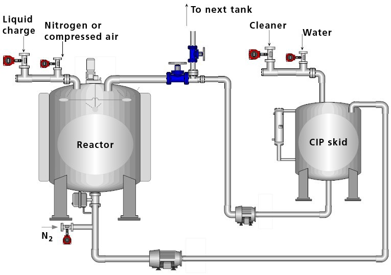
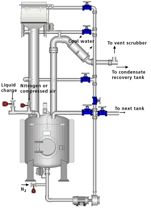
A CIP system includes equipment and various components. These systems can be fully or semiautomated for minimal operator intervention. They can be fixed installations or portable systems that clean several pieces of equipment in the same manufacturing train. Figure 1 shows a fixed CIP skid unit connected to manufacturing equipment. CIP systems can also be designed and integrated into the equipment itself. Figure 2 illustrates a large vessel with the necessary components to perform cleaning without a separate CIP unit. All cleaning steps, particularly cleaning solution preparation and heating, are performed in the same process vessel. |
Figure 1: Simplified scheme of a clean-in-place skid connected to a manufacturing vessel. Image is courtesy of the author. |
 |
Figure 2: Simplified scheme of a clean-in-place system embedded into the manufacturing vessel. Image is courtesy of the author. |
Materials of construction
Materials used for GMP equipment must be easy to clean, corrosion-resistant, and nonreactive under manufacturing and cleaning-process conditions. Surfaces should have a smooth appearance and be fabricated appropriately with materials that are adequate for the process. Processing equipment is primarily made of 304- or 316-grade stainless steel and with glass or hastelloy. Seals, gaskets, and closures are made with plastic and elastomers that are suitable for the intended application.
For optimal cleaning, surfaces must be free of scratches, crevices, etching, and irregularities. Polished surfaces with roughness of Ra ≤ 1.6 µm have been recommended particularly for the biotechnology industry to facilitate cleaning (1, 2). Nonetheless, recent studies suggest that surface cleanability is most affected by surface defects, rather than surface roughness (3).
Piping and process connections
Welding is the preferred method for connecting piping that handles product and transfers cleaning solutions. A properly welded connection should not have excessive cracks, crevices, misalignments, or other surface deformities that contribute to corrosion. In the case of temporary joints used for maintenance or multiprocess reconfigurations, sanitary clamp-type connections are universally accepted for joining two similar end pieces with a centered elastomeric gasket. Variations of the clamp-type connection have also been developed for high-pressure applications. Flanged and cam-type connections must be avoided because their sealing material may not align adequately and may eventually collect residues in the gasket area.
Diaphragm and pinch valves are most often recommended and are generally considered sanitary valves. Other types of valves (e.g., ball, gate, and butterfly valves) entail contamination risk by accumulating soil and debris at gasket spindles and crevices, so they are difficult to clean in place. Ball valves used to manufacture active ingredients are commonly located at the bottom of large vessels because they can withstand high pressures. If a ball valve is installed, specific instructions should be included in the process cleaning procedure for dismantling and visually inspecting the ball valve once CIP cleaning is completed. Additional manual cleaning steps and sampling for cleanliness may also be necessary.
Dead legs, pitch, and pumps
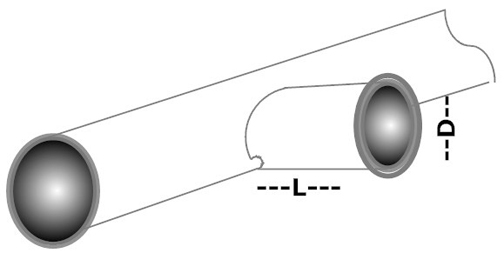
Dead legs are areas in a piping system where liquid or gas can become stagnant and where water is not exchanged during flushing. For obvious reasons, dead legs should be minimized or, if possible, avoided in CIP piping. Bacteria and soil in dead-end pipe lengths and crevices are protected from flushing and sanitization procedures and eventually can contaminate the piping system. Dead-ends in piping are unacceptable unless they can be physically inspected and sampled for cleanliness. Branches or tees used for instrumentation should be positioned horizontally, and their length should be limited to 1.5 times the pipe diameter. Figure 3 depicts a dead leg and its recommended orientation.
 |
Figure 3: Recommended dead-leg orientation to minimize bubbles, soil, and debris entrapment. Image is courtesy of the author. |
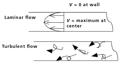
Personnel can clean piping effectively by circulating the cleaning solution at flow rates that produce turbulent flow conditions. Usually, CIP flow rates are much higher than the flows used for manufacturing processes. The Reynolds number (Re) determines whether a flow is laminar or turbulent. This dimensionless number describes the expected velocity profile for a fluid flowing under certain parameters. For a fluid running in a circular piping, Re can be calculated with the following equation:
Re = DρV
µ
where D is the pipe diameter, ρ is the fluid density, V is the fluid mean velocity, and µ is the fluid viscosity. Re numbers higher than 4000 produce turbulence that creates random eddies, vortices, and other flow instabilities that exert mechanical action on the pipe walls (4). Random eddies are better than smooth, constant fluid motion because they promote mixing and help prevent soil redeposition (see Figure 4). Most CIP designers would recommend a fluid velocity of approximately 5 ft/s (1.5 m/s) for water-based solutions to displace gases, penetrate dead legs, and fill vertical piping.
 |
Figure 4. Velocity profiles for flow in a tubular pipe. Image is courtesy of the author. |
Horizontal ductwork must be sloped at 1/16 to 1/8 in. per foot of piping (0.5 to 1 cm per meter of piping). The pitch must be toward drain points.
Pumps should be cleaned in line with the piping circuitry. When a pump is not required to operate in the CIP circuit, the flow may be directed through a bypass. In general, the hygienic attributes of a pump are the materials of construction for its main pump chamber and sealing points. With a few exceptions, pumps typically include a sealing mechanism on the rotating shaft. Most hygienic pumps have seal mechanisms outside the product-contact zone with minimal elastomeric exposure to product and cleaning solution.
Tanks, internal components, and ancillary equipment
Pharmaceuticals can be processed in vessels of various shapes, sizes, and configurations. If they are to be cleaned in place, processing tanks must have a conical dome and a bottom that facilitates draining. Flat bottoms, which are rare in pharmaceutical applications, need to have bottom or side drain ports. Side drain ports must be located below the end of the side wall, and the tank should be sloped toward the drain. For good results, the vessel must drain liquid at the same rate that it takes in liquid. These same principles should also be followed for CIP skid tanks.
The bottom outlet nozzle of a vessel typically requires a vortex breaker to prevent the swirling of flow. Disc and X-type breakers are most common and are easy to CIP.
Nozzle design should follow the same sanitary guidance as that discussed for piping. The length-to-diameter ratio should be close to 1.5, and the nozzle should be located on top of the vessel. For example, pressure-relief devices such as rupture discs are easier to clean when mounted directly onto the nozzle, rather than on an extension pipe. Tank insulation may affect nozzle design and may require a flared nozzle. Side ports must be sloped toward the drain point.
Spray devices
Personnel can clean tanks effectively by distributing cleaning solutions with spray devices (5, 6). Various models are available, including static devices (e.g., spray balls, spray tubes, and spray bubbles) and dynamic devices that can rotate on multiple axes. Spray devices can cover large surface areas in vessels, charge chutes, vent lines, and pipes larger than 8 in. (20 cm) in diameter. In vessels, static spray devices direct the solution to the top dome, from where it cascades down in a sheeting action. In comparison, dynamic spray devices operate at relatively high pressures and rotate at various angles to produce surface impingement.
All CIP spray devices should contain drain ports that allow them to clean themselves. Periodic inspection is recommended to ensure that the spray holes are not clogged with particles and debris that can affect spray coverage and pressure.
The flow rate required to achieve the proper spray and cascading effect is 2.5 gpm per foot (31.1 L/min per meter) of vessel perimeter in a vertical tank and 0.25 gpm per square foot (10.2 L/min per square meter) of surface area in a horizontal tank. Baffles, dip tubes, nozzles, or agitators in a tank challenge the cleaning process by preventing sprayed fluid from striking the far side of the vessel walls. When these mechanical items are present, additional spray devices may be necessary to reach protrusions and shadowed areas.
Many types of agitators are available for specific manufacturing applications. Agitators with pitched blades can be cleaned with the tank-spray devices. Other types of agitators (e.g., Rushton impellers) may require spray devices below the impeller to ensure thorough cleaning. Other options for cleaning agitator blades may include immersing them in cleaning solution and adding mechanical agitation to facilitate soil removal.
The most effective way to clean vent lines, condensers, charge–discharge chutes, and ancillary equipment is by direct application of CIP solution from a spray device. Bubble sprayers connected to permanent or semipermanent CIP pipes spray upward and across to form falling films that sweep away soils.
Transfer panels play an important role in CIP systems. They are metal boards with an array of nozzles that connect multiple pipelines. Transfer panels supply and change the flow of cleaning fluids through CIP pipelines linked to multiple process machines within piping circuitry. A transfer-panel jumper, or U-bend, helps to break the flow between fluids used in manufacturing without the risk of cross-contamination.
Note: Part I of this article appeared in the June issue of Equipment & Processing Report.
References
- European Committee for Standardization, DS/EN 13311-1: Biotechnology–Performance Criteria for Vessels Part 1: General Performance Criteria (Brussels, Jun. 2001), pp. 1–13.
- Y. Chisti and M. Moo-Young, J. Ind. Microbiol. 13 (4), 201–207 (1994).
- F. Riedewald, PDA J. Pharm. Sci. Technol. 60 (3), 164–171 (2006).
- R.H. Perry and D.W. Green, Perry’s Chemical Engineers’ Handbook (McGraw-Hill, New York, 8th ed., 2008), pp. 1–56.
- N. Fletcher, Cleanroom Technol. Oct. 7, 18–20 (2008).
- N. Fletcher, Cleanroom Technol. Dec. 18, 21–23 (2008).
Elizabeth Rivera is a technical service specialist for STERIS, 7405 Page Ave., St. Louis, MO 63133, tel. 314.290.4783, fax 314.290.4650, erivera@steris.com.